Idea:
Every one uses electronics, specially this small ICs and pieces. Keeping the place steady in the manufacuring process is an important thing to consider, as the crowded place makes it even harder to find things easily and waste much time in the manufacturing processes. We decided to make a simple, well organized and reliable project to ensure the clean and organized environment.
In this page, we will focus more on the drawer.
Step 1: Assuming the drawer dimensions
After a discussion with the team responsible on designing the container, we decided to make the drawer dimension 40x40 mm and 70mm depth, all dimensions are considered with the joints (outer)

Step 2: Drawing
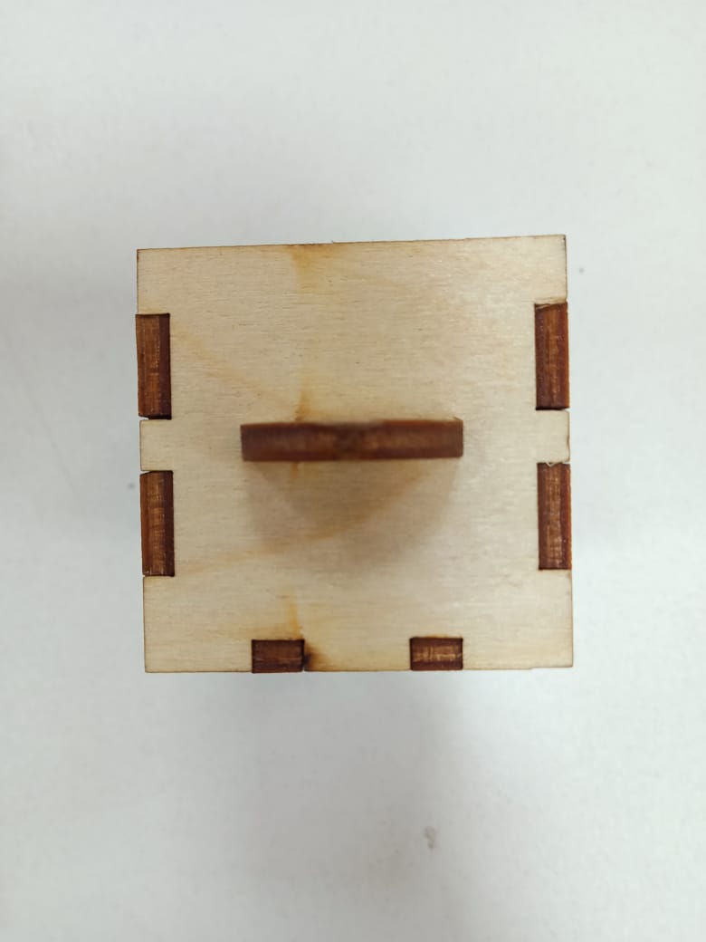
First I decided to make the drawer with finger joints, and the challenge for me was how to make a holder for the drawer that isn't loose and fixed. I decided to apply the design introduce to us in the presentation, as it locks by rotating and one the holder is locked; it will never be saperated from the drawer as shown in this slide
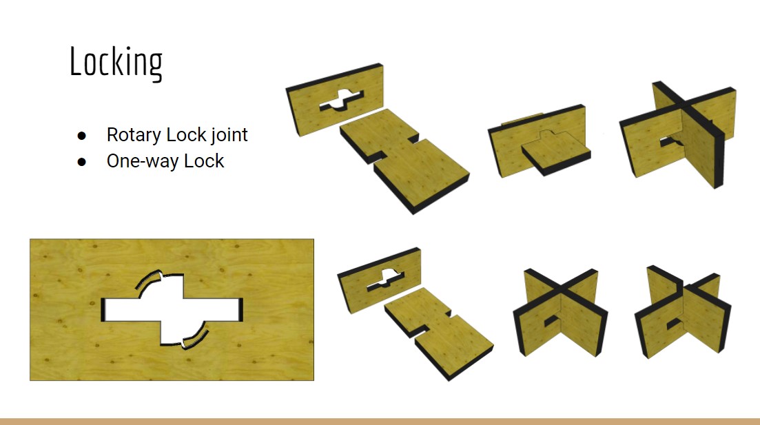
I decided to apply this design to the drawer holder and drew it on solidworks
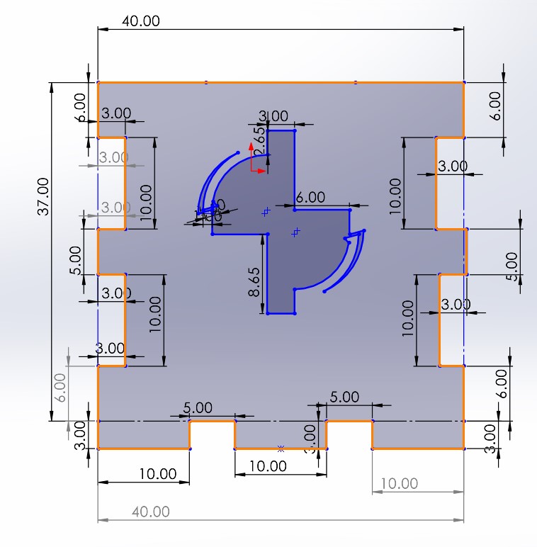
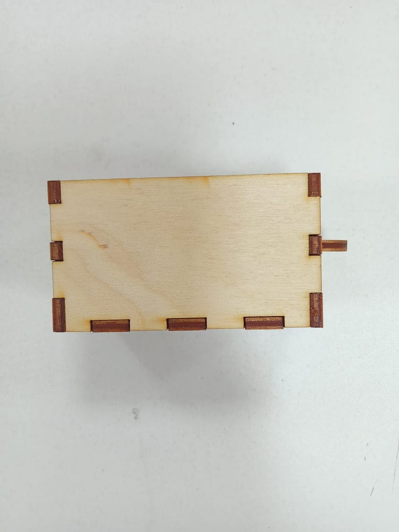
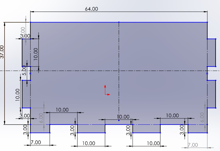
For the Sides and base I designed them to be fixed together with finger joints as shown with the dimensions mentioned before
Step 3: From .STL to machin file
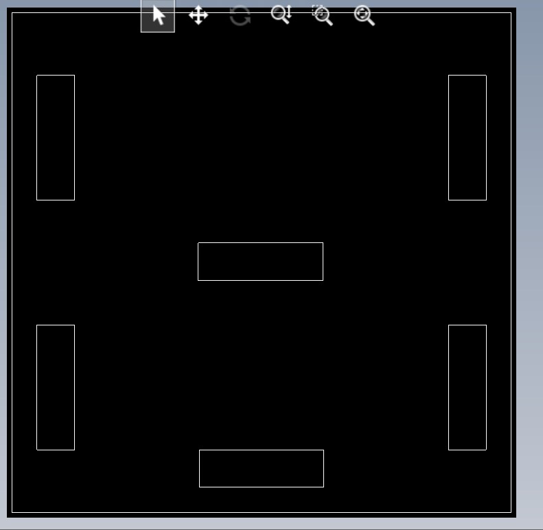
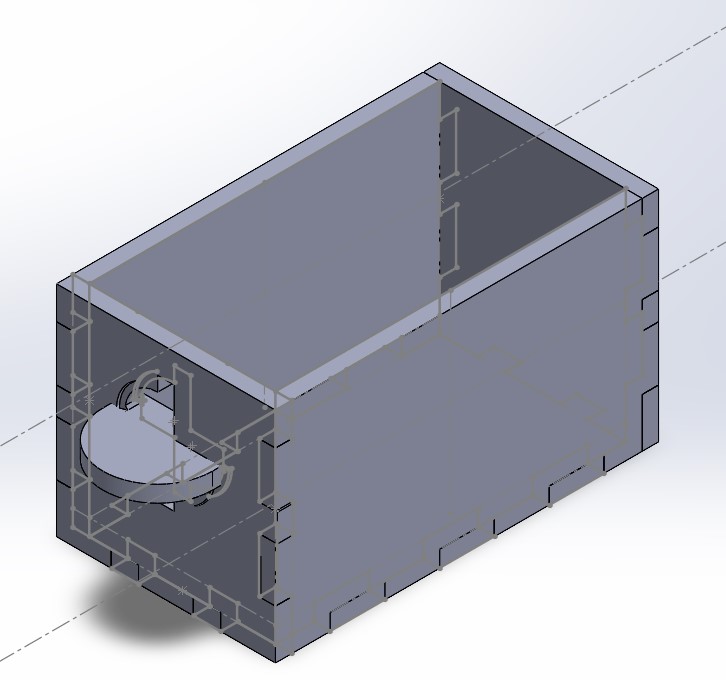
Then After finishing your parts, I made an assembly to assure the dimensions. Then I exported all the files to dxf extensions Inorder to be ready for RDworks software. I imported the dxf files to the RDworks software which is a cam software to print them on the laser cutting machine
Step 4: Cutting
After cutting the parts, it turns out the the dimensions of locking is too thin as they were broken when I tried to lock it first time. Also, the karf made by the raduis of focal point of the laser cutter made a space between the finger joints of the parts... that made them loose and not fixed
Step 5: redesining
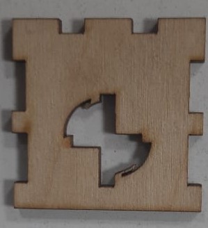
After discovering all the faults, I tried to make a new design that could solve the holder and karf issues. I tried another type of joints, whose idea is to make a total fraction between two parts by making a hole in a part to fit the another. After repeating the drawing and cutting process, this was the results:
Step 6: redsigning again :')
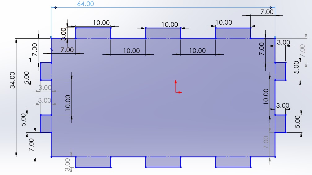
Foe the previous result, I tried to get back to the first design that used the finger joints, but this time I will try to fix them by adding the karf length to the dimensions to be fixed tight even after cutting. After some experiments, the kart was estimated to be 0.3mm. I added this dimension to my parts in solid works and repeated the drawing and cutting process. Here is an assembly for the design:
Step 5: Testing
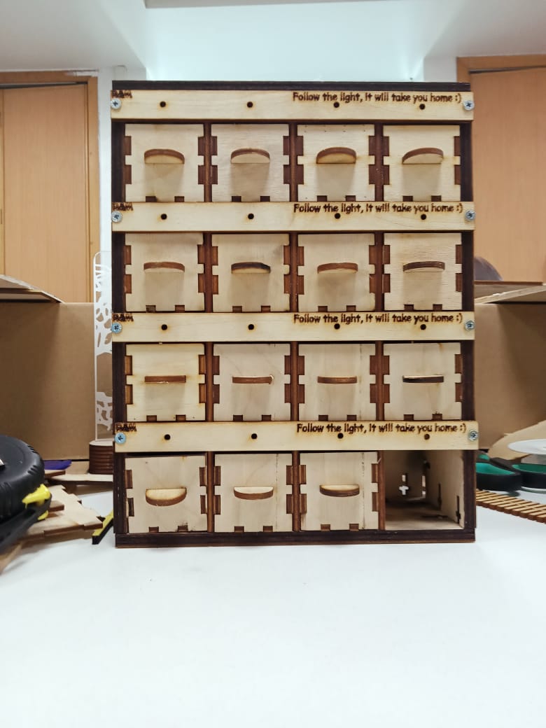
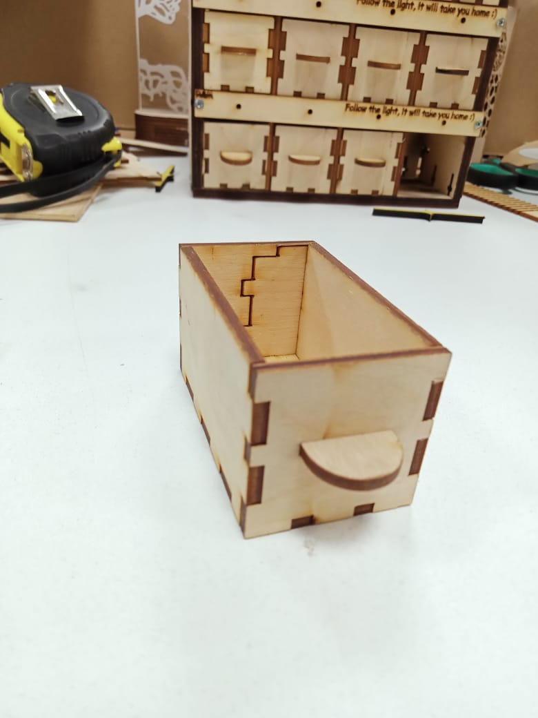
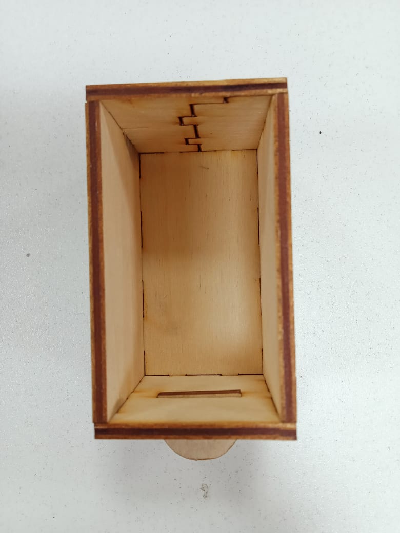
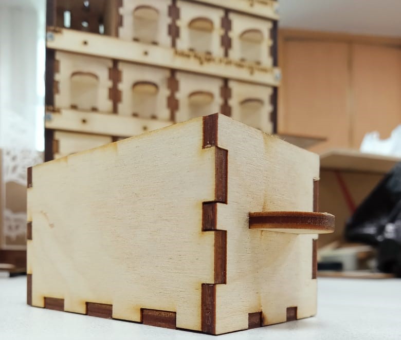
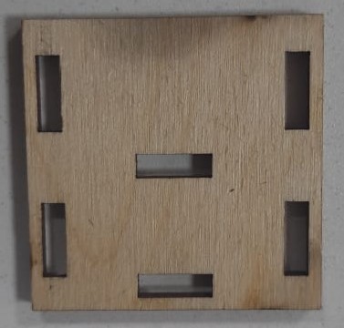
After applying the last design and cutting it, it finally came out with the design requirement. The parts are fixed tight together and its exactly the same dimensions as the countainer holes. Here are some images for the results.
Final product